Ok, continuing our journey through the network stack downwards we just reached the transport layer, where some of the magics behind the scenes happen. This layer is where two of the most well known protocols are, being them TCP (Transmission Control Protocol) and UDP (User Datagram Protocol).
These two protocols are used to the same purpose: provide a way to two different applications (i.e. a HTTP client and a server) to communicate between them accross the whole internet (or even in the same [local] system).
With that said, the single question arises: how the hell these guys work?. And that is exactly what I am going to try to explain and show you.
TCP and UDP internals
These two protocols are intended to work for the same main purpose, as stated earlier, but they defer tremendously when comes to “controlling” the connection itself, being that one - TCP - tries to keep the connection as reliable as possible and transparent to the application, while the other - UDP - just give up from everything on behalf of simplicity and performance, leaving the burden of implementing some of the controlling mechanisms to the user’s application, if desired.
The way both protocols keep track of application’s address is through port numbers, which are controlled by the operating system and have a finite amount available (16 bits = 65535). These ports are basically how house/street numbers work: if you wish to talk to someone in a specific house, you need to reach him in that specific number, but, at the same time, the application must be waiting (listening) for someone in that specific port to allow the communication to happen.
But wait, before we start to digress about that in a really high level, lets take a look in how these information are organized, one protocol at a time, to highlight the differences between them.
TCP - Overview (RFC 793)
The first thing to know is that each step downwards the stack a few bytes are added to our whole packet size. That is due to header fields that are being prefixed/suffixed each time a protocol manipulates it. For instance, TCP protocol might add to our packet’s length up to 60 bytes of information.
Below is an image representing all header fields available:
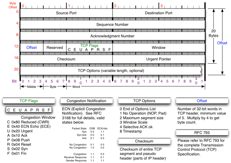
As the protocol’s name already states, TCP is basically a protocol to control the delivery of packets through the network to end user applications. What most shines herein is the fact that TCP guarantees certain principles to the application layer, these being:
- Connection establishment;
- Reliable data transfer, through:
- sequence number (SEQ) header field;
- acknowledgement number (ACK) header field;
- Flow control mechanism:
- Using window field.
- Bandwidth congestion control mechanism, through:
- ACK field and some internal timers.
As you can see, all the headers are basically used to control and handle a transparent communication channel among applications within the internet.
But at the same time, why is these guarantees even necessary? Well, basically because the internet itself is not a reliable system: it has uncountable failures down the road with bogus systems, malfunctioning equipment, broken or totally filled/busy links, and so forth. Depending on the channel being used to transmit the packet it might be pretty hard to reach a destination application, geographically distance, without hitting a single issue and that is the reasoning behind all these control flags, fields and mechanisms.
It is also valid to remember that although the network stack still have more protocols underneath transport layer, TCP is the one caring the responsibility to deliver a transparent and reliable network to the application.
Now, lets talk about these three guarantees.
TCP - Connection establishment
This step is also known as handshake, which provides enough information to keep the connection open and alive until one of the parts closes it. This step brings some guarantees that help and can facilitate the architecture behind the next protocol’s features.
Although many people don’t really pay attention to this step I think it’s worth mentioning since some networking security issues are directly related to it. But at the same time, I won’t getting in much detail about the security aspect of that, it’s subject for another whole series of posts.
Before the handshake starts the server side of the connection must bind to and listen to a specific port on its system. Once it’s ready for receiving connections (represented to a call to the listen() system call) the client can actively open a connection to the server by calling the connect() system call. The connection request is then received by the server system which waits for a direct call to accept() from the server application, and once it’s issued the 3-way handshake can start.
3-way handshake
This handshake set the values for both directions packets’ sequence numbers, which has its first value set randomly and also guarantees both sides are aware that if they wish to finish the connection they must start the termination process, and not just drop the other without any warnings (although it doesn’t prevent on endpoint or another to drop due to connection issues).
At client active open connection time a SYN packet is sent to the server with a
random sequence number ($SEQ_{cli}$) chosen by the client. The server then
sends a reply, SYN+ACK packet, with its acknowledgment number set to the
clients sequence number plus one ($SEQ_{cli} + 1$), and the packet sequence
number is also set to a randomly generated number ($SEQ_{server}$). Then,
finally, the client replies with an ACK packet containing the acknowledge
number set to $SEQ_{server} + 1$ and the sequence number set to $SEQ_{cli} +
1$.
As I said before, this process helps to keep the connection alive, but at the same time open some security holes allowing attackers perform attacks like DoS, issuing multiple SYN packets at the same time. But hey, that’s a concern for another post. Lets move on.
TCP - Reliable Data Transfer
As I said before, there are three variables being monitored to keep the data transfer between applications reliable: packet’s sequence number, acknowledgment number and the mechanism of flow control, which basically checks for the window size field together with the other two variables.
Sequence number
Lets consider the sequence number first chosen in the handshake were 0 for both directions, this will make our discussion easier, it represents the order in which such packet was sent, being the number the last byte of that packet counted since the beginning of the whole data being sent.
For example, consider a data of a thousand bytes, which was decided to be fragmented in ten smaller packets of a hundred bytes each:
$$1000{bytes} = 10\times 100{bytes}$$
For each chunk of 100 bytes the sequence number is increased by that amount in that specific packet.
Acknowledgment number
This number is used in the ACK packet, which determines the last packet’s
sequence number received. If the last packet received had SEQ equivalent to
200, than the acknowledgment number for the ACK packet will be $200 + 1 =
201$, meaning that the packet with SEQ 200 was received and it’s now waiting
for the next packet starting from SEQ 201.
Flow control
Flow control take in consideration the remaining size of sender’s data buffer, represented by the window field in the header, in other words, how many bytes are still left to be filled in the sender’s data queue, thus the other side of the connection know how many bytes he can send within the next packet without overflowing the buffer for that sender.
Bundling the last window number with both last SEQ and ACK number it’s possible to avoid flow issues due to overflowing buffers and, consequently, duplicate packets in the channel due to retransmission.
TCP - Congestion control
As a starting point, TCP tries to avoid any unnecessary data transmission between connection endpoints with the go-back-n approach, which specifies an amount of bytes the sender can send before require waiting for an ACK packet from receiver.
But the real congestion control happens with the increase of this maximum amount of bytes not acknowledged in transit threshold, which is doubled each time the sender successfully receives the receiver’s ACK (process known as slow start), until to the point a doubled ACK (meaning the last data sent was not received) happens and the threshold is then dropped by half of the current value, thus dropping the data transmission and possibly helping controlling the channel congestion.
The following picture helps to understand the above statement about the threshold, took from the Computer Network book from Kurose & Ross.
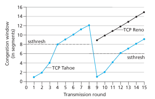
Just for your information, there are more than one algorithms of TCP congestion control, each one might have a different focus, resulting in different behaviors. As you can see in the last picture, there were two different implementations of congestion control algorithms, being one TCP Tahoe and the another Reno.
UDP - Overview (RFC 768)
Different from what we have seen about TCP, UDP is the smaller and simpler one. Its focus is basically in performance. All the controlling mechanisms are left to the application layer handle, in case it feels it’s necessary somehow.
And as you may see in the header image below the UDP header doesn’t have anything else other than the basic fields that a transport protocol should handle: source and destination port, the length of the header and the checksum of the whole datagram.
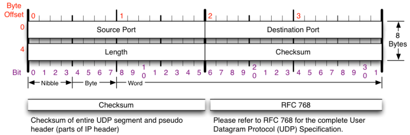
Because of that there isn’t much to say about the UDP other than: it is the materialization of the most basic concept of what can be a transport layer protocol, there aren’t any kind of guarantee regarding delivery or link in which the packets are being transmitted.
This might seem something bad, or that should never be used, but that’s not true. There are multiple use cases where UDP is desirable, mostly where some packet losses aren’t much important or where the application has some kind of data correction.
As the time passes the link quality available for normal users are getting cheaper and better, making many UDP users migrate to TCP, since the overhead added are relatively also getting cheaper. That’s more a judgment call considering your project’s specifications.
Recap from application layer packet
We are now going to take the results we got in part 1 of this series and literally encapsulate it within the, what is called, payload from transport layer protocol’s segment.
Stack analysis
Using HTTP client side of our application and remembering that HTTP protocols uses TCP protocol as its transport layer, the request content that will be held by TCP’s payload is:
> GET / HTTP/1.1
> Host: 127.0.0.1:8080
> User-Agent: curl/7.61.1
> Accept: */*
And to manually check this payload content to the most low level perspective, we can use the tcpdump tool to monitor the network interface (lo in this case, since we are working with localhost) for all incoming and outgoing packets in a transport layer point of view, while sending requests to the server:
# tcpdump --dont-verify-checksums -i lo -X -n -v 'port 8080'
NOTE: the
--dont-verify-checksumsoption was used to hide checksum errors from output. It’s required due to the checksum offloading my operating system is performing letting the checksum creation responsibility to the network device instead of the os’ TCP stack.
19:03:15.252021 IP (tos 0x0, ttl 64, id 31238, offset 0, flags [DF], proto TCP (6), length 130)
    127.0.0.1.44328 > 127.0.0.1.webcache: Flags [P.], seq 1:79, ack 1, win 512, options [nop,nop,TS val 420155347 ecr 420155347], length 78: HTTP, length: 78
        GET / HTTP/1.1
        Host: localhost:8080
        User-Agent: curl/7.65.3
        Accept: */*

        0x0000:  4500 0082 7a06 4000 4006 c26d 7f00 0001  E...z.@.@..m....
        0x0010:  7f00 0001 ad28 1f90 0ef2 af63 f20b 1b81  .....(.....c....
        0x0020:  8018 0200 fe76 0000 0101 080a 190b 0fd3  .....v..........
        0x0030:  190b 0fd3 4745 5420 2f20 4854 5450 2f31  ....GET./.HTTP/1
        0x0040:  2e31 0d0a 486f 7374 3a20 6c6f 6361 6c68  .1..Host:.localh
        0x0050:  6f73 743a 3830 3830 0d0a 5573 6572 2d41  ost:8080..User-A
        0x0060:  6765 6e74 3a20 6375 726c 2f37 2e36 352e  gent:.curl/7.65.
        0x0070:  330d 0a41 6363 6570 743a 202a 2f2a 0d0a  3..Accept:.*/*..
        0x0080:  0d0a                                     ..
NOTE: just as a matter of clarification, you can see the string “127.0.0.1.webcache” representing the packet destination address (server IP address and TCP port): webcache is a default port name set in /etc/services file as an alias to the port number 8080 that is being listened by our HTTP server.
$ grep webcache /etc/services
webcache        8080/tcp        http-alt        # WWW caching service
webcache        8080/udp        http-alt        # WWW caching service
Now, right in the same output from tcpdump we can also get the servers reply data:
19:03:15.254766 IP (tos 0x0, ttl 64, id 52968, offset 0, flags [DF], proto TCP (6), length 139)
    127.0.0.1.webcache > 127.0.0.1.44328: Flags [P.], seq 1:88, ack 79, win 512, options [nop,nop,TS val 420155350 ecr 420155347], length 87: HTTP, length: 87
        HTTP/1.1 200 OK
        Content-Length: 22
        Content-Type: text/plain

        You have requested: /
        0x0000:  4500 008b cee8 4000 4006 6d82 7f00 0001  E.....@.@.m.....
        0x0010:  7f00 0001 1f90 ad28 f20b 1b81 0ef2 afb1  .......(........
        0x0020:  8018 0200 fe7f 0000 0101 080a 190b 0fd6  ................
        0x0030:  190b 0fd3 4854 5450 2f31 2e31 2032 3030  ....HTTP/1.1.200
        0x0040:  204f 4b0d 0a43 6f6e 7465 6e74 2d4c 656e  .OK..Content-Len
        0x0050:  6774 683a 2032 320d 0a43 6f6e 7465 6e74  gth:.22..Content
        0x0060:  2d54 7970 653a 2074 6578 742f 706c 6169  -Type:.text/plai
        0x0070:  6e0d 0a0d 0a59 6f75 2068 6176 6520 7265  n....You.have.re
        0x0080:  7175 6573 7465 643a 202f 0a              quested:./.
If we start checking all bytes/bits of both segments we’re going to see that the values there present matches the values presented by tcpdump output in the second line, where flags, seq, ack, win, options and length are all TCP header fields and its values are decoded.
Before we finish, just for your information, the tcpdump command I used prompted many other packets other than these two I presented above, those other packets are the SYNs and FINs used to connection establishment and ending respectively. I won’t describe then in here, but will let it as exercise for those interested. Also, reading the manpage of the tool you’re going to see a way for avoiding them from being prompted.
Now that we have seen either application and transport layers it’s time to dive into the network layer, where the most well known protocol is placed: Internet Protocol (IP).